HOME ELECTRICAL WIRING BASICS
Whether you are considering a backup power system, want to add another electric circuit, or are going to install a new appliance, it is important to understand the home’s electrical wiring basics and applicable codes.

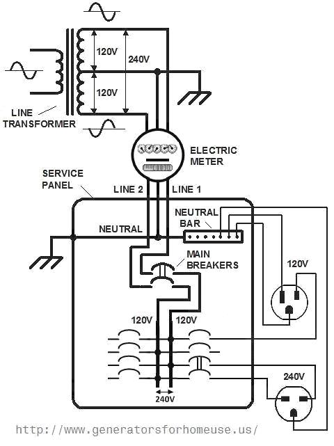
First, let’s briefly review how electricity gets to your house. Most residential and light commercial homes in U.S. have a single-phase 3-wire 120V/240V service. It consists of two inverted relative to each other lines and a grounded neutral. Connecting an electric load between any line and the neutral yields 120 volts AC. Connecting between both lines yields 240 volts AC (see the diagram). The two 120V buses are derived from a step-down distribution transformer, which is usually mounted on a pole. Its secondary winding has a grounded center tap connected to neutral wire. The two end terminals are electrically “hot” with respect to the neutral. Note that both lines are derived from the same utility phase. That’s why such configuration is often called “split phase” (it’s not a two-phase circuit as some incorrectly call it). The three conductors go from the pole to your electric meter. From the meter they run to the panel containing the main service disconnect. From there the lines go to magnetic circuit breakers that protect individual branches. The branch breakers can be mounted in a separate distribution panel or can be incorporated into the main panel. The individual outlets in the homes are normally NEMA 5-15R duplex. The National Electric Code (NEC®) 2023 specifies the locations in dwelling units where the outlets should have GFCI (article 210.8). Particularly, GFCI should be in bathrooms, garages, kitchens, etc.
The article 210.12 additionally requires special arc-fault circuit interrupters (AFCI) for most types of rooms. Of course, if you don’t do any changes, you are not required to upgrade, but if you modify, replace, or extend any branch-circuit, you are supposed to add an AFCI either at the beginning of that branch or at its first outlet.
Why, you may ask, do we need a 3-wire configuration? Would not a single 120V bus be enough? The case is, a standard wall outlet NEMA 5-15R is rated to 15A. Hence, the maximum power you can draw from such an outlet is 15×120=1800 volt-amps. Moreover, for continuous loads, NEC® recommends limiting the current on receptacles to 80%. Therefore, steady state current should be less than 12A (which corresponds to 120×12=1440 VA).
What if your appliance consumes more power? There are of course high-current receptacles, such as twist-lock 125 Volt 30 Amp NEMA L5-30R. However, large appliances such as a central a/c or driers are usually designed to work from 240V. This is done in order to reduce energy losses in the cables. Remember, power is volts times amps. When you double the voltage, you need half the current to deliver the same wattage. And for lower currents you can use lower conductor thickness. That’s the main reason we are getting 240V. As you can see from this wiring diagram, it is obtained from two 120VAC lines, so we have two voltage levels. Of course, in theory, if most small residential appliances were not designed for 120V, we could do away with it and use a more efficient 240V or any other higher voltage system. As we know, Europe and most other countries employ 220-240V wiring. Historically, U.S. initially adapted a lower potential level mainly because the original Edison’s electric bulbs were optimized for 110V. Later on, it was raised to 120V. Note that the total electric current consumed by your home is split between two lines and you should try to balance your loads.
Note that the receptacle’s rating is not the only factor that limits the amount of current you can draw from it. Often, each breaker serves several outlets. The allowable amperage is therefore also limited by the rating of the breakers and the size of the wires. The continuous electric load on each circuit should not exceed 80% of the breaker ratings per Table 210.21(B)(2) of NFPA70®. The branch conductors should be rated 125% of the maximum load.
As you can see from the above diagram, the standard receptacles have an additional ground terminal. It connects to the neutral bus in the breaker panel, which in turn is bonded to earth. In those devices that are powered via 3-lead cords, this wire grounds the case of the device. In the past, appliances did not use a safety ground wire and just had the neutral bonded to their cases. Likewise, old outlets, which can still be found in many homes, had two holes instead of three.
NOTE. The information in this site is provided AS IS for technical reference only without guarantee and liability of any type, neither explicit or implicit. It expresses only the personal opinion of the author and does not constitute professional advice- see complete disclaimer linked below. Most works related to circuit wiring, panels and hard-wired appliances usually requires a permit and should be performed by a licensed electrician.
